
![]()
by Peter Birren, with lots of help from Don Hewett, Dan Hartowicz, Warren Seipman and others
(Click on a name to go there or just scroll down and read along)
The two major parts of a static line tension sensing system are:
1. Hydraulic Cylinder |
2. Gauge
Other parts include:
3. Hose |
4. Fluid |
5. Fittings |
6. Attachments
Then when it's all together it has to be:
7: Tested Elements:
Other considerations:
8. Emergency Release
9. Photos of the system
![]()
This is mostly a how-to on putting together the parts of a static towing system for hang gliders and paragliders, though some of it could apply to other types of towing. I've tried to "hide" it from casual web browsers but still make it available to serious pilots ready to make the move to towing.
If you have no experience towing a hang glider, much less flying one, seek instruction before attempting to fly. We (all the participants in the sport) don't want you to die because of doing something stupid like buying a glider at a garage sale and going to a hill and trying this all on your own. Be smart. Get instruction.
Before I go into the parts of a system similar to mine, a little history: Donnell Hewett realized in the early 80's that towing without knowing the different tensions, or how best to apply the tensions to the glider, was causing fatal accidents and breaking said gliders. The typical setup was to wrap the towline around the base tube and this caused many gliders to lockout and dive into the ground out of control.
Don's first job was to devise a bridle that allowed for most control of the glider. This was accomplished with a 2:1 "pulley" bridle that attaches to the center-of-mass of the pilot and Cm of the glider. The bridle attachment points, materials, etc., could be the subject of a different article; Bill Bryden and Dennis Pagen have done so in the book Towing Aloft.
During the testing of the bridles, Don had his wife, Helen, and daughter would hold a short towline while he soared the dunes near Corpus Christie TX. They could be seen "walking" their dad along the beach much like a kid playing with his kite. Eventually the size, type and placement of the bridle was settled on and Don went about figuring how to control the towline tension.
His original and very functional device used a coiled garage door spring inside a PVC tube. The spring had a tab on it that stuck through a slot in the tube. This assembly was attached to their car's front bumper with Helen holding the tube while in the driver's seat. The tension was ideal when the tab hit her thumb. Don progressed, with the help of a few others, to replacing the spring with a simple hydraulic system.
Over the next few months various tensions were tried, and minimums and maximums were found. These are still in use today. Don feels most accomplished with this development moreso than for the bridle which carries his name – the Hewett Center-of-Mass Bridle. He feels that the tension sensing device is a much more important contribution to towing safety than anything else.
1. Hydraulic cylinder
Hydraulic is somewhat of a misnomer as this is actually a pneumatic cylinder but it pushes hydraulic fluid (Baby Oil, see point #4). The type we used for more than 25 years with great success is a Double-Action, Pivot-Mount, Stainless Steel-body Air Cylinder. Bore = 1.25" (gives about 1" square surface area for what amounts to a 1:1 reading at the gauge). Larger bore = lower reading at the gauge. Stroke = 1" to 2" (shorter is better to limit shaft bending)
The "pivot mount" means it has a hole on the back end that will accept 1/4" Perlon, 1" tubular webbing or a U-joint for a flexible mount. The shaft is often threaded on the end to accept any of several types of line attachment devices.
We also found the Humphrey Model #25-DP-11/2 works (when a good one is found).
Dave Broyles uses a Bimba 500 hydraulic cylinder, 1 1/16” diameter. This hydraulic cylinder has two ports, one for out-stroke or push, and one for in-stroke or pull. To use it to measure pull, you have to use the side with the shaft. There is a hole on each end, one for push and one for pull.
![]()
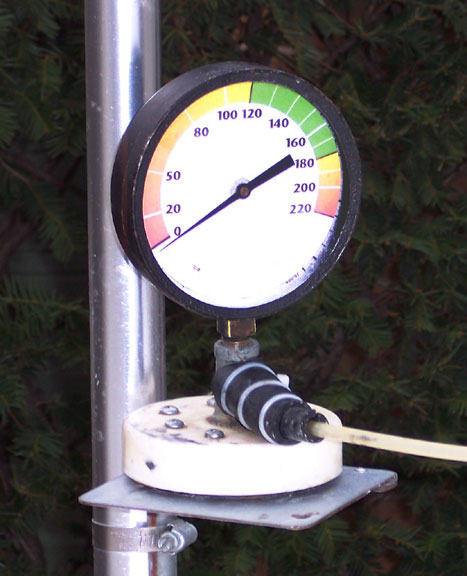
The gauge must work in concert with the cylinder to read 300 pounds for solo pilot and 400 pounds if towing tandems. Such a high reading is so the system does not bottom out with the driver thinking all is OK. Gauge should have a large 4" face with polycarbonate (Lexan) cover plate. You can replace the dial faceplate with your own after hanging weights to test the system. Testing at various weights will also uncover any leaks in the system. (see #8 below).
These sketches are from my system. Gauge has to be mounted so the driver can easily keep an eye on it while driving, but style does count.
Split rubber tubing in several layers was added
to help prevent crimping of the pressure hose.
![]()
The T-fitting, plastic cap and speaker magnet are all "potted" with a generous application of epoxy. Adding a piece of thin adhesive vinyl or a layer of packaging tape will mostly protect from scratching painted surfaces.
A decent gauge is Grainger's "Mechanical Contractor's Lead Gauge" from Ametek. It's got a 4.5" face and 1/4" ANPT fitting. Stock number WWG-1X734, Cost = $16.00. (2023: can't find it right off now).
![]()
I wasn't able to find a stock number on the hose though I've been told it's a 400# test clear hydraulic line, available from most hardware stores. This seems a little light duty but worked fine for years of solo towing. You'll need a little more than 20 feet (better to have too much than too little). This will allow the gauge to mount on the hood of the car or on another base of your choice and the cylinder to attach to the rear bumper.
![]()
Johnson's Baby Oil is what most reel owners I know use. If there's a leak in the hose, the baby oil won't eat the paint as will hydraulic or brake fluid. Saw a break happen once when someone set up the hose strangely and it got caught in the car door. The baby oil wiped up without problem.
![]()
Do not use "tool-less" fittings anywhere in the system. These have a tendency to come undone at the most inopportune time. Use the regular threaded brass fittings available wherever you buy the cylinder. They're pretty easy to work with and are quite inexpensive, so buy more than you need to make up a repair kit and for the mistakes that will happen.
On the cylinder, make sure the "intake" has a screen filter (or better) to prevent dust and dirt from shortening its life. I suggest you also use some old fuel line or various sized rubber hose to create strain relief layers at both the gauge and cylinder. These are the areas that take the most abuse, especially when rolling up the hose to put away after a day of flying.
Use your imagination to mount the gauge to a CB-antenna magnet; a speaker magnet will do also. The hose should come out horizontally above the mag-base.
Some snap-in fittings are reported to work well with very little loss of fluid. I have yet to see or work with 'em but look forward to reporting back when I do.
![]()
This is <my> setup. Yours can certainly be different as long as it works.
Gauge should be mounted in the driver's line of sight, preferably so s/he doesn't have to look anywhere but straight ahead.
Cylinder needs a couple of attachments: one to the bumper to provide complete freedom of movement – up, down, sideways – without interference. The other is a safety to some point above in case the bumper attachment comes loose for whatever reason. This secondary line also should keep the cylinder from dragging on the ground, and must not interfere with its normal operation.
To allow the towline to easily be put on and taken off the cylinder shaft, I use a spring-loaded 1/4" snap link welded to a bolt, then double-bolted on the shaft. Another system uses a sailing shackle that doubles as an emergency release, similar to the one used at Wallaby/Quest for a glider keel release that opens all the way. Again, you can be creative but make it bulletproof and functional.
When the system is placed on the car/truck, route the hose under one windshield wiper arm and over the cab to keep it from getting caught in a door or anything else.
![]()
Once the system is assembled and all bubbles have been removed from the hose, now comes the fun. By using a variety of weights, including your body weight, hang test and record the main and secondary tension points on the gauge, then other weight amounts inbetween. When using any given weight, bounce it and/or let it sit for a while so you don't get just the first reading. Remove the weights to let all go back to zero, then add more. Or use a light weight, then a max weight, then another test on a light weight, all to make certain that you're reading as accurately as possible over multiple tests.
This is one of my early gauge templates. Every year I hang weights to test the system and, if necessary, make a new paper faceplate and apply with SprayMount.
During testing, I tape a sheet of clear acetate to the gauge face and use a grease pencil for the marks, then use a protractor and computer drawing program to make a replacement face plate that gets taped behind the needle. Here are the weights/tensions and colors as I use 'em:
WHITE –- 0 - 20 Take up slack
RED –- 20 - 100 pounds for launch tension: GO, GO, GO
YELLOW – 100 - 120 Average launch tension
GREEN –- 120 - 180 Stay on the low side until MAX is requested
YELLOW – 180 - 200 Upper warning area
RED –--- 200 - 265 (obvious?) weaklink break area, uncomfortable.
![]()
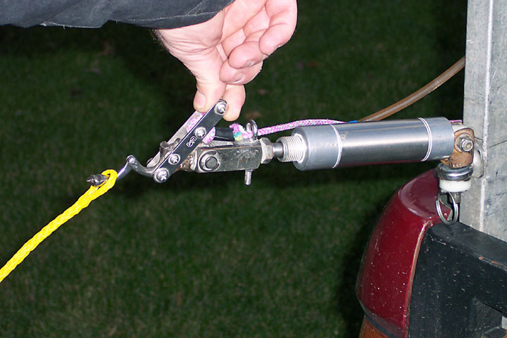
The Reel Pilots suggest some form of release at the car be used when training newer pilots, those with less than -say- 25 successful, PIO-free tows and obviously in full control. There are a couple of drawbacks however, like if the release is triggered, the towline could snag on something on the ground and possibly be more of a hazard than if it was not released. There have been maybe 3 instances in 20 years of towing with our group where it migh have been handy to have this setup.
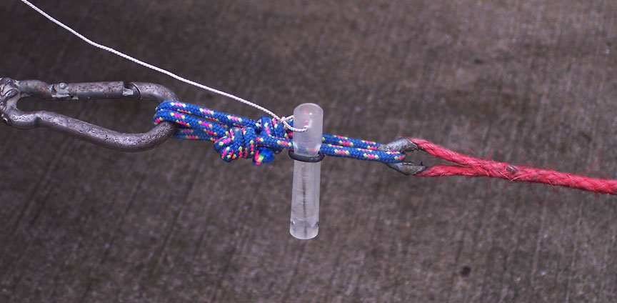
The Linknife is one way of making an emergency release that is activated by the driver.
Here's Chris DeLannoy's setup using a sailing shackle:
More system photos HERE.
Previous situations – problems that could have been prevented.
The jury's still out on the absolute need for a release at the vehicle for tows involving other than newer or low-time pilots. No reel owner I know has used one, ever, as the vast majority of tows involve highly experienced pilots. However, we're getting more new pilots involved and may make an emergency release an SOP. If you have any questions or suggestions to improve any of the above, please write and let me know.
One situation resulted in the fatality of a student pilot on 3rd solo tow. No one may ever know what really happened but she seemed to just freeze at 200 feet above the ground (using 1500 feet of towline). Pilot slowly turned into a classic lockout and dove straight in without ever reaching for the release or correcting for the turn. Tragic to the max. A release at the vehicle, or possibly something like a Pitch Limiter, might have kept it from being fatal.
A pilot (flying only a couple of times per year, if that) had a release lockup while on a pulley tow, had no hook knife and no radio – he came in from 750' – and it's possible that releasing from the car might have helped... maybe not, however, as the line could possibly have snagged in the pulley.
Another incident involved no less than 7 errors (radio problems, no weaklink, almost-hang-3 pilot, launching on highly thermic day through a slot in trees, using homemade 1-string release, with a fast-handling glider), so dropping the line from the vehicle might or might not have helped. Incident resulted in the pilot being hospitalized.
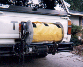
Thanks to Rich Sacher for building a wonderful reel design
used by many of the Reel Pilots. If memory serves, at one
time there were 18 of these reels owned by club members.
![]()
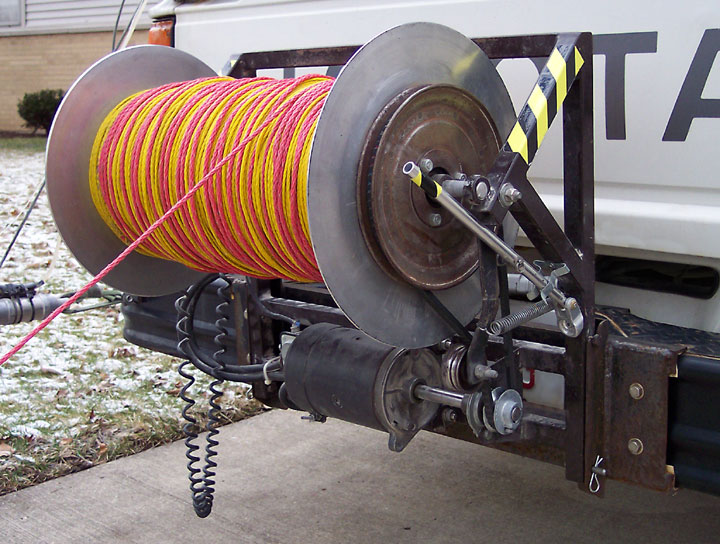
12V long shaft starter motor, welded commutators and end-shaft bearings through continuous duty golf cart solenoid. Plugs into car battery using #2 welding cable with fork lift charging plugs to connect/disconnect the reel. Cables stay connected to the battery for the entire flying season but disconnected during the winter as road salt causes heavy corrosion. Spool has aluminum side plates bolted to a 6" PVC spool base with internal bearings on the solid axle - spool could be mounted solidly to the axle if pillow blocks are used on the frame. Bottom bracket is semi-permantently mounted to the truck. Reel is held in place at the top with welded-on bolt heads on the reel which fit into slots on the mounting brackets and, at the bottom, with 2 trailer pins.
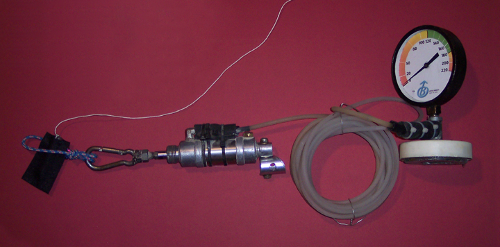
Magnetically mounted gauge and roll of high-pressure tubing.
![]()
NEXT PAGES:
General overview
Parts of the system
Bridle info
Driver info
Towing criteria
Linknife Static Tow
DISCLAIMER: As with all aviation endeavors, your choice and use of equipment is totally up to you. It is assumed you are an experienced HG or PG tow pilot who is intimately familiar with the style of towing you will be doing. As such, YOU ASSUME ALL RISK AND LIABILITY in the use of the Linknife, as well as all other parts, functions and personnel involved in the towing and flight operations. If you do not have experience in towing, please contact an instructor for expert training. Trying to learn on your own can, and probably will, result in your injury and even death. Many pilots have paid the ultimate price so we may now tow as safely as never before possible. Please learn from their lessons.
Linknife Home | Static Line | Payout/Platform | Aerotow | Testimonials
Reel Pilots Home |
Hewett's Towing Criteria |
Driver SOP
Static Line Basics |
Static Towing Parts |
Hewett Bridle Basics
Parachutes |
Lockouts |
Payout Primer |
Flying Sites
Links clubs/info |
Links2 states/countries
Airshow |
Site Opening Primer
Birren Design Company | Site Map
©2000-2023 Peter Birren email
Powered by w3.css